Frequently Asked Questions

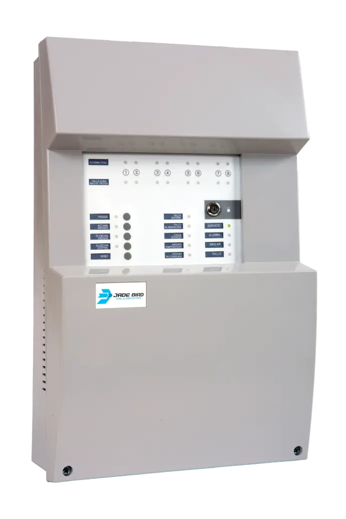
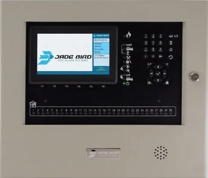
Draco Panel JBE-P2L1
Possible Cause
The wiring is open at some point in the installation. There is no physical return to the Draco panel in installations configured as Class A (closed loop).Poor contact or faulty connection of a short-circuit isolator at its base.
Recommended Solution
- If the installation is designed as a loop (Class A), physically check that the return cable is correctly connected to the relevant terminals on the panel.
- Check that all JBE-2150 loop isolator modules are firmly seated in their sockets.
- To isolate the cut section, temporarily change the configuration to Class B (no return) in the settings menu and check the signal report to see which devices stop responding, in order to locate the cut point.
Possible Cause
The panel has detected two or more physical devices configured with the same address on the same loop.
Recommended Solution
- Use the control unit’s reporting tool: go to F3. REPORTS -> 9. View addresses used in a loop to identify occupied and free addresses.
- Using the JBE-AT1 handheld programmer, you can force the LED on the relevant devices to light up, enabling you to locate them visually within the installation.
- Change the address of one of the duplicate devices to a free loop address using the JBE-AT1 programmer.
Possible Cause
A device has been connected to the loop but has not been registered in the panel’s logical configuration.
Recommended Solution
- Recommended option: Go to the INSTALL menu and perform an Auto-Register devices so that the control panel automatically recognises and integrates the new equipment into the database.
- Manual option: Go to the ADJUST menu -> 1. Manual device registration and de-register and manually enter the exact loop, address and device type. Once you have finished, reset the system.
Possible Cause
There is a discrepancy between the type of physical device installed at an address and the type logically registered in the control panel’s programming.
Recommended Solution
- Quick option: Run ‘Auto-Register Devices’ in the INSTALL menu to automatically update the device type on the panel.
- Manual option: Go to the SETTINGS menu and manually change the device type assigned to that address so that it exactly matches the physical device installed (for example, changing an optical detector to a thermal one).
Possible Cause
No 24 Vdc auxiliary power supply or reversed polarity in the power supply wiring.
Recommended Solution
- Check that the polarity of the 24V line is correct: 24V (+) and GND (-).
- If the line is powered from the Draco control unit, check that the auxiliary voltage output from the panel is correct.
- If you are using an external power supply, check that it is receiving a mains supply of 230 V AC and that the output is operational.
Possible Cause
The end-of-line monitoring resistor is missing, damaged or has an incorrect value.
Recommended Solution
- Please ensure that the mandatory 10 kΩ terminating resistor is correctly fitted to the input/output monitoring terminals.
Conventional Panel
Possible Cause
The control panel is not receiving power
Recommended Solution
- Check that 230 VAC mains voltage is present at the installation input.
- Check the control panel's mains fuse (250 VAC - 4A).
- Check that the batteries are properly connected and that the battery fuse (2A) is not blown.
Possible Cause
There is a problem with the power supply sources or internal fuses
Recommended Solution
- Measure the battery voltage with a multimeter. It should be above 24 VDC.
- Check that the cable link connecting the two 12 V batteries in series is correctly connected.
- Check the condition of the mains and battery fuses, as well as the sounder and 24 V auxiliary outputs
Possible Cause
There is a physical fault on the detection line of the affected zone
Recommended Solution
- Using a multimeter, check that the end-of-line resistor at the end of the zone is exactly 4.7 kΩ.
- Check for short circuits or open circuits in the zone wiring.
- Make sure that no detectors are installed with reversed polarity in their bases.
- Check whether any manual call point has been activated and does not have an internal alarm resistor.
Possible Cause
There is a physical fault on the sounder output lines
Recommended Solution
- Check that a 4.7 kΩ end-of-line resistor is installed on the supervised sounder lines [159, 196].
- Check for short circuits or open circuits in the wiring [197].
- Make sure that no conventional sounder is connected with reversed polarity.
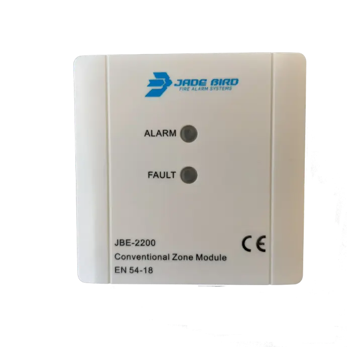
Conventional Zone Module (JBE-2200)
The JBE-2200 conventional zone module uses a dedicated orange FAULT LED to indicate faults through different flashing patterns:
- LED Steady ON: Open Circuit. The supervised 4.7 kΩ end-of-line resistor is not installed, is damaged, or the conventional zone line is open at some point.
- 1 Flash per Second: Low Voltage. The conventional zone line supply voltage is insufficient to ensure proper operation.
- 2 Flashes per Second: Short Circuit. A resistance close to 0 Ω has been detected, or a conventional detector or manual call point is incorrectly connected to the line.
- Continuous Rapid Flashing: Overcurrent. Too many conventional detectors are installed on the conventional zone, exceeding the maximum current load permitted by the module.
- 3-Second Flashing: Reset Process. Indicates that the module is performing a zone reset and temporarily disconnecting power from the conventional detectors to reset them.
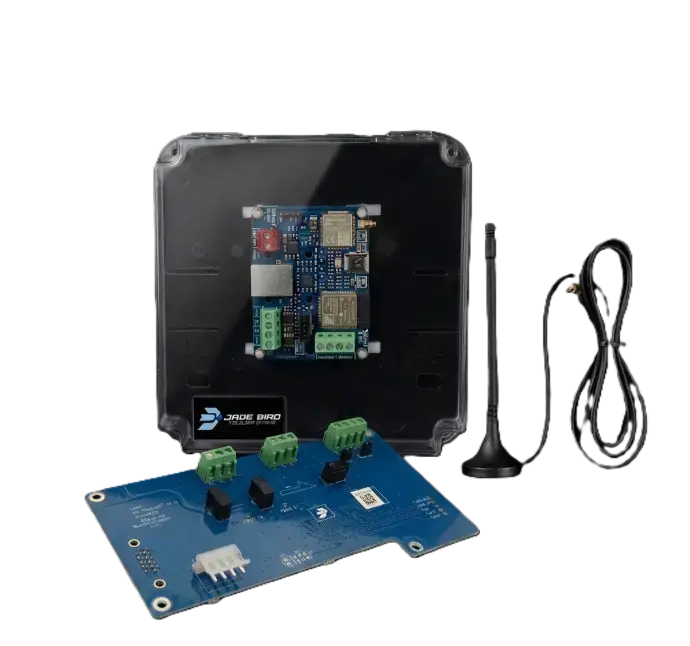
SisCom Communication Transmitters (F25 / FB2)
- Cause: Reversed power supply polarity or voltage outside the permitted range.
- Solution: Check that the power supply wiring is connected to the fire alarm control panel's 24V Aux output, with the correct polarity, and that the voltage is within the range of 5 VDC to 30 VDC.
- Cause: Reversed power supply polarity or voltage outside the permitted range.
- Solution: Check that the power supply wiring is connected to the fire alarm control panel's 24V Aux output, with the correct polarity, and that the voltage is within the range of 5 VDC to 30 VDC.
- Cause: Incorrect APN, username, or password settings for the SIM card operator.
- Solution: Access the transmitter configuration and check that the APN, Username, and Password parameters exactly match those provided by the mobile network operator. The use of dedicated M2M SIM cards with a flat-rate data plan of at least 1 GB/month is recommended.
- Cause: Incorrect IP address or port, or local network issues.
- Solution: Check that the Main IP address (or DNS) and Input Port of the receiving centre configured in the transmitter are correct. If a wired Ethernet (LAN) connection is used, check that DHCP is enabled to automatically obtain the network parameters, or verify that the manual settings (static IP address, subnet mask, and gateway) have been correctly provided by the site's network administrator.
FREQUENTLY ASKED QUESTIONS (FAQ)
The Draco control panel has restricted access security levels to prevent unauthorized operation:
- Level 1 (Public/Firefighters): No password is required. Allows the internal buzzer to be silenced and basic status reports to be viewed.
- Level 2 (Authorized User): The factory default password is 111 (3 digits). Provides access to reset functions, zone tests, indicator tests, keypad tests, and device or zone disablement.
- Level 3 (Installer/Maintenance): The factory default password is 1111111111 (10 ones). Provides access to advanced system configuration, device-to-zone assignment, cause-and-effect logic for outputs, and delay settings.
- Display update note: The code used to access the firmware update screen via the USB port is 111111111 (10 ones).
The Draco control panel uses sealed 12 V lead-acid batteries connected in series (24 VDC nominal), and two new batteries of the same capacity must always be installed as a pair:
- In the main control panel enclosure: Either 7 Ah (Yuasa NP7-12LFR) or 12 Ah (Yuasa NP12-12FR) batteries can be installed. Both battery models require a 6.3 mm Faston terminal connector.
- In the optional external auxiliary battery box (JBE-BAT): This enclosure accommodates higher-capacity batteries, specifically 17 Ah (Yuasa NP17-12IFR). In this case, the required connection terminal is 5 mm.
- For conventional control panels (JBE-C2Z/C4Z): Two 12 V batteries connected in series are required, with a capacity of 2.3 Ah.
The addressable detection loop of the Draco control panel supports a maximum cable distance of up to 2,000 metres. The manufacturer requires the use of 2 x 1.5 mm² twisted-pair cable without shielding. The JBE intelligent bus is non-polarized for field devices, which greatly simplifies installation and prevents faults caused by reversed cable connections on the loop.
It depends on the physical transmission medium used for the network:
- Copper cable (JBE-P2L2-NET network card): The maximum network distance between control panels is 1,000 metres, using 2 x 1.5 mm² twisted-pair cable without shielding. This network card allows up to 16 nodes (control panels) to be interconnected in the same ring.
- Optical fibre (JBE-2595 converter): Allows the panel communication network to be extended over distances of up to 40 kilometres using dual single-mode optical fibre with SC connectors.
Each addressable loop of the Draco control panel supports a maximum of 200 logical addresses (which may include detectors, manual call points, input or output modules, and addressable sounders). A single Draco control panel can be expanded using JBE-P2L2-2LP loop expansion cards up to a maximum of 8 loops, allowing a total maximum of 1,600 addressable devices per control panel.
It depends on the line and equipment being supervised:
- Conventional control panel JBE-C2Z / JBE-C4Z: Both conventional detector zone lines and sounder outputs require 4.7 kΩ resistors.
- JBE-2200 analogue conventional zone module: Requires a 4.7 kΩ end-of-line resistor on the supervised conventional zone.
- Analogue input/output modules (JBE-2120 / JBE-2125): Require a 10 kΩ end-of-line resistor for contact or line supervision.
After confirming that the alarm condition has ended and that there is no actual danger:
- Unlock the keypad: Insert the physical key into the control panel's front key switch or enter the Level 2 password.
- Silence the buzzer and sounders: Press the Panel Silence button to silence the internal buzzer and Sounders Silence or Sounders OFF/ON on the panel.
- Perform the reset: Press the RESET button. This temporarily cuts power to the loop for approximately 9 seconds to reset the automatic detectors and return the system to its normal standby condition.